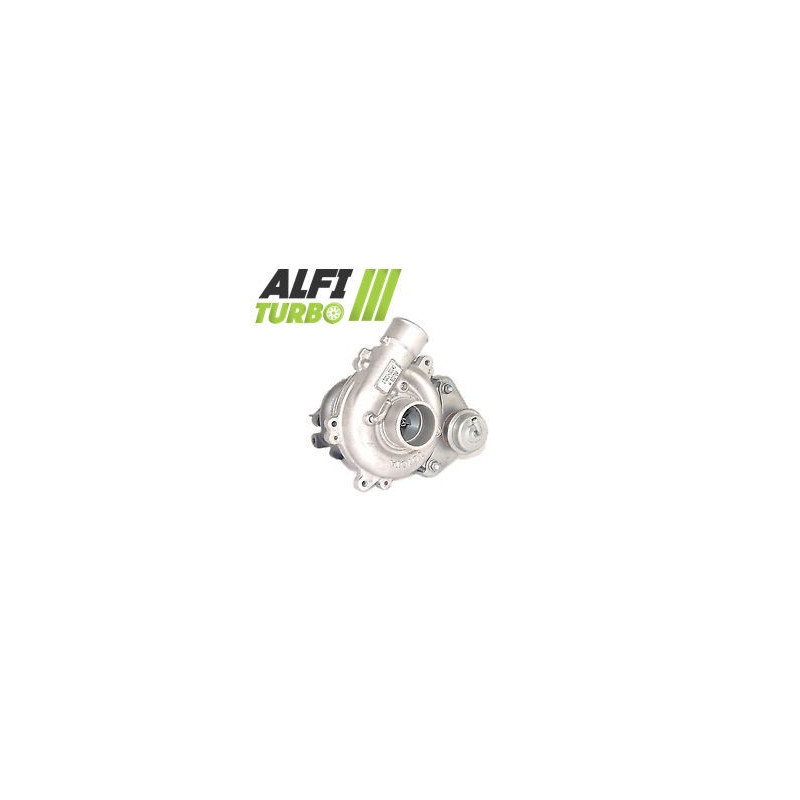
This hybrid turbo for, fitted to a 2.5- D engine producing 120 hp, is designed using the plug & play architecture, enabling Installation without modification. . Three levels of tuning are documented to d adapt the internal components to the engine project’s objectives.
The configurations are based in particular on a high-flow MFS compressor wheel, a 360° bearing stop and high-speed balancing on a Cimat VSR bench.
Available configurations — Stage 1, Stage 2 and Stage 3
Stage 1
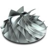
Compressor impeller: High-flow MFS
Thrust bearing: 360° thrust bearing
Balancing: High-speed balancing at 150,000 rpm on a Cimat VSR bench
This configuration combines a high-flow MFS compressor impeller with a 360° thrust bearing. It is designed to adapt the compression capacity and air flow rate d whilst retaining the documented casing configuration.
Stage 2
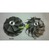
Compressor impeller: High-flow MFS oversized
d intake housing: Reprofiled for accommodate the new impeller oversized
Thrust bearing: 360° thrust bearing
Balancing: High-speed balancing at 150,000 rpm on a Cimat VSR test bench
oversized ’s compressor impeller requires the intake housing to be re-profiled d. This configuration can move more air d under the right conditions, but its performance depends on the overall tuning of the engine.
Stage 3
Compressor impeller: High-flow MFS oversized
Casing d'intake: Reprofiled for accommodate the new impeller oversized
Thrust bearing: 360° thrust bearing
Turbine impeller: High-flow and oversized
Turbine housing: Reprofiled for ly to accommodate the new impeller oversized
Balancing: High-speed balancing at 150,000 rpm on a Cimat VSR test bench
This upgrade adds a oversized turbine impeller and involves the re-profiling of its housing. These modifications affect the flow rates on both the compressor and exhaust sides, as well as the turbocharger’s behaviour and response time.
What is a hybrid turbo?
A hybrid turbo utilises a turbocharger architecture adapted for to accommodate modified internal components. Depending on the stage, the modifications may involve the compressor wheel, the housings, the turbine wheel, the thrust bearing system and balancing.
The aim is d to adapt the compression capacity and air flow rate d. However, a hybrid turbo is not defined solely by the appearance of its compressor wheel: the compatibility between the wheels, housings and engine management system remains crucial.
MFS compressor wheel: standard or Performance?
MFS stands for ‘Milled From Solid’, meaning a wheel machined from a solid block. This is d'a manufacturing process which, on its own, does not guarantee an increase in air flow d'air. A standard MFS wheel may retain a geometry close to the d'original.
An MFS impeller Performance may utilise a geometry adapted to the application, with a specific profile or dimensions, provided these modifications are documented. A standard MFS impeller can be just as shiny as an MFS impeller Performance. It is not its appearance that determines its performance, but its geometry and its ability to move more d'air.
Why does the geometry of the blades influence the air flow rate d?
The impeller’s diameter, profile, height, width and blade arrangement all influence the intake and compression of air. The right geometry can increase air flow under certain conditions, but the result also depends on the housings, the turbine, the boost pressure and the mapping. A larger impeller therefore does not automatically guarantee better performance and may alter the response time.
Reliability and balancing of the hybrid turbocharger
The documented 360° thrust bearing distributes axial forces over a larger surface area. Balancing the rotor at 150,000 rpm on a Cimat VSR test bench helps to limit vibrations and mechanical stresses, though it does not compensate for poor installation or inadequate lubrication.
Engine remapping and preparation
Appropriate engine management is required for to make the most of the hybrid turbo’s characteristics. The mapping, boost pressure, fuel supply, exhaust, intake air cooling d and transmission must be controlled in accordance with the project. The wastegate must be adjusted when remapping the ECU. No power gain can be guaranteed without a coherent engine configuration.
Turbo specifications
Documented OEM and manufacturer part numbers
17201-30141
1720130141
17201-30140
1720130140
Compatible vehicles and applications
Automotive applications
No specific fitment is documented. Compatibility must be confirmed using the original turbo part number d.
Additional technical specifications
Product type: Hybrid Turbo
Engine: 2.5 D
Power: 120 hp
Installation: Plug & play, no modifications required
Installation advice
⚠️ WARNING — IMPORTANT BEFORE INSTALLATION
Identify and rectify the cause of the previous fault. Check the lubrication circuit, as well as the oil supply and return d. Check that the pipes are clean, the inlet and that there are no foreign objects. Prime the system in accordance with the applicable recommendations and follow the manufacturer’s instructions. A lubrication fault that is not rectified may lead to further turbocharger failure.
How do you identify the correct turbo?
Check the turbo’s part number d, the original, OEM and manufacturer part numbers, the model, generation, body style, engine type, power output,Year and engine code.. An identical engine type does not always guarantee compatibility.
⚠️ Check your turbo’s part numbers
Before ordering, compare the part number marked on your original turbo d with the part numbers listed in this product description. An identical engine specification does not always guarantee compatibility. If in doubt, please contact us before ordering.