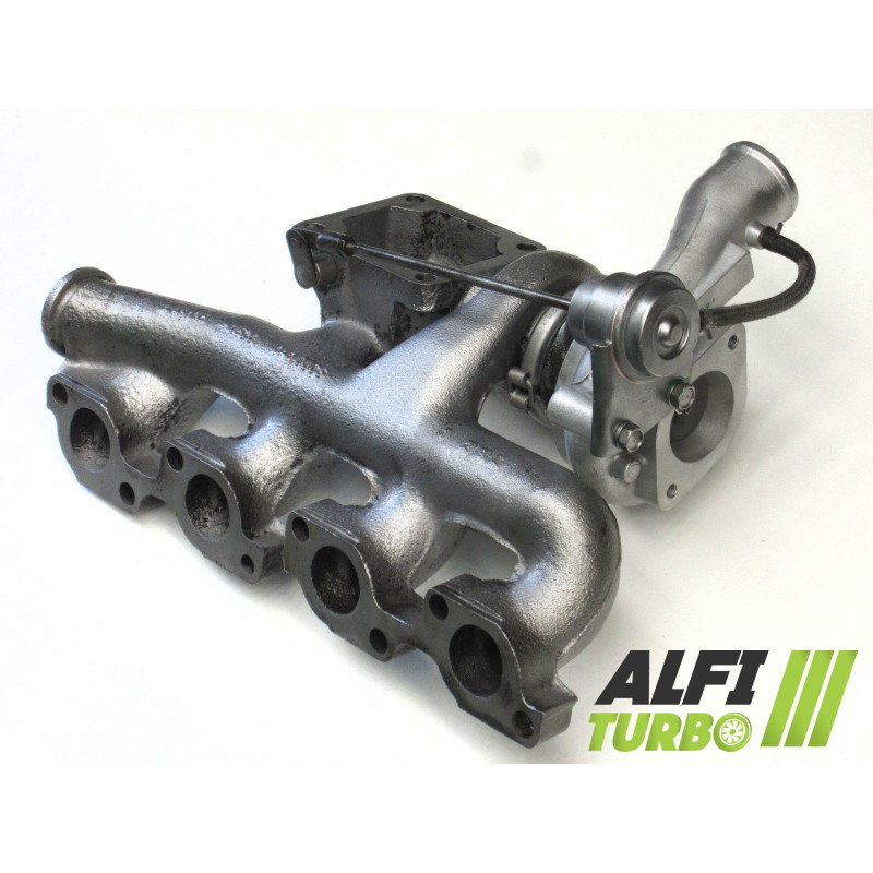
This hybrid turbo for, designed for the Ford Transit 2.4 TDCI, features da tuning programme aimed at increasing dair flow. Depending on the chosen package, it combines a high-flow MFS compressor wheel, a 360° bearing stop and additional modifications to the wheels and housings.
The documented applications relate to the rear-wheel-drive versions of the 75, 90, 120 and 125 hp from 2000 onwards. The configuration is designed for for an external Installation without modification, subject to verification of the original turbocharger’s part numbers d.
Available upgrades — Stage 1, Stage 2 and Stage 3
Stage 1
Compressor wheel: MFS high-flow
Thrustbearing: 360° thrust bearing
Balancing: High-speed balancing at 150,000 rpm on a Cimat VSR test bench
This modification primarily affects the compressor section in order dto adapt its capacity to move and compress air. Its operation must remain consistent with the engine management system and the vehicle’s peripheral components.
Stage 2
Compressor impeller: MFS high-flow oversized
d’ intake housing: Reprofiled for accommodate the new impeller oversized
Thrustbearing: 360° thrust bearing
Balancing: High-speed balancing at 150,000 rpm on a Cimat VSR test bench
The Stage 2 combines a oversized compressor wheel with a reprofiled dintake casing. This adaptation is designed to make the most of the new geometry whilst maintaining a mechanically coherent assembly.
Stage 3
Compressor impeller: MFS high-flow oversized
dintake housing: Reprofiled for accommodate the new impeller oversized
Thrustbearing: 360° thrust bearing
Turbine impeller: High-flow oversized
Turbine casing: Reprofiled for ly to accommodate the new impeller oversized
Balancing: High-speed balancing at 150,000 rpm on a Cimat VSR test bench
Stage 3 modifies the compressor and turbine sides. The final performance depends on the overall engine configuration; a larger impeller alone does not guarantee better performance under all conditions.
Understanding hybrid tuning
What is a hybrid turbo?
A hybrid turbo is based on an architecture adapted for to accommodate internal components that differ from the original dconfiguration. Depending on the stage, modifications may involve the compressor wheel, the housings, the turbine wheel, the thrust bearing and balancing. Their aim is dto adapt the compression capacity and the air flow rate d; the appearance of the impeller is therefore not sufficient to determine the level of preparation.
MFS compressor impeller: standard or ‘ Performance ’?
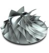
MFS stands for ‘Milled From Solid’, meaning a wheel machined from a solid block. A standard MFS wheel may retain a geometry equivalent to the original: the manufacturing process or a polished finish do not necessarily indicate an increase in flow rate. An MFS ‘ Performance ’ impeller can be given a geometry suited to the tuning. A standard MFS impeller can be just as polished as an MFS ‘ Performance ’ impeller. It is not its appearance that determines its performance, but its geometry and its ability to move more dair.
Why does the geometry of the blades influence the airflow d?
The diameter of the impeller, the profile, height, width and arrangement of the blades all influence the intake and compression of air. The result also depends on the casings, the turbine wheel, the boost pressure and the engine tuning. An increase in size can also alter the response time and the range dof optimal use.
Reliability and balancing of the hybrid turbocharger
The documented 360° thrust bearing distributes axial forces over a wide surface area. Balancing the rotor at 150,000 rpm on a Cimat VSR test bench helps to limit vibrations and mechanical stresses, though it does not compensate for inadequate lubrication or incorrect installation.
Engine remapping and preparation
To make the most of the hybrid turbo’s characteristics, the mapping and boost pressure may need to be adjusted. The injection, exhaust, cooling, the clutch or the transmission must be checked depending on the level of tuning. The wastegate must be adjusted when remapping the ECU. No power gain is automatic without appropriate engine configuration.
Turbo specifications
OEM part numbers
Ford
3C1Q-6K682-EB
3C1Q-6K682-FB
3C1Q6K682EA
3C1Q6K682FB
YC1O6K682AD
YC1Q6K682AD
Manufacturer’s part numbers
49135-06010
49135-06015
49135-06017
Compatible vehicles and configurations
Ford
Transit 2000 rear-wheel drive — 75 hp
2.4 TDCI — from 2000, end date unspecified
Engine code : unspecified
Transit 2000 rear-wheel drive — 90 hp
2.4 TDCI — from 2000, end date unspecified
Engine code : unspecified
Transit 2000 rear-wheel drive — 120 hp
2.4 TDCI — from 2000, end date unspecified
Engine code : unspecified
Transit 2000 rear-wheel drive — 125 hp
2.4 TDCI — from 2000, end date unspecified
Engine code : unspecified
Additional technical specifications
Product type: Hybrid Turbo
Motorisation: 2.4 TDCI
Documented power outputs: 75, 90, 120 and 125 hp
Production period: From 2000, end unspecified
Installation: Configured as ‘ plug & play ’, with no external modifications
Fitting advice
⚠️ WARNING — IMPORTANT BEFORE INSTALLATIONIdentify and rectify the cause of the previous fault. Check the lubrication circuit, as well as the oil supply and return d. Check that the pipes are clean, the inlet and that there are no foreign objects. Carry out priming in accordance with the applicable recommendations and follow the manufacturer’s instructions.
Failure to rectify a lubrication fault may result in the turbocharger failing again.
How do you identify the correct turbo?
Check the turbo part number dof the original unit, the OEM and manufacturer part numbers, as well as the make, model, drivetrain version, engine type (2.4 TDCI), power output andYear mounting configuration. An identical engine type does not always guarantee compatibility.
⚠️ Check your turbo’s part numbersBefore ordering, compare the part number marked on your original turbo d with the part numbers listed in this data sheet. An identical engine specification does not always guarantee compatibility.
If in doubt, please contact us with the part number found on your turbocharger.